

Introduction of Sacrificial Anode Cathodic Protection
HOME > Introduction to Cathodic protection > Introduction of Sacrificial Anode Cathodic Protection
Types of cathodic protection methods
| Element | Secrificial anode system | Impressed current system |
|---|---|---|
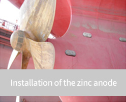
| types of cathodic protection methods | Mg Anode, Al Anode, Zn Anode | H.S.C.I Anode, M.M.O Anode |
| construction method | - | Deep Well Bed, Shallow Bed |
| pros |
|
|
| cons |
|
|
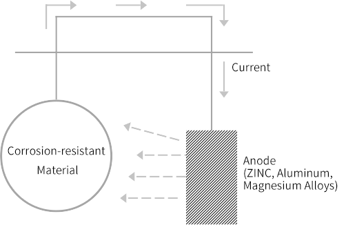
Secrificial Anode Cathodic Protection
By connecting the metal with lower potential to the protected strcutre within the corrosive environment, either directly or through a wire, an electrochemical reaction occurs between the two metals. This results in the extraction of metal ions from the anode, generating a current. The lower potential metal, serving as the sacrificial anode, is consumed sacrificially instead of the protected structure, preventing corrosion.
Sacrificial anode construction procedure

By connecting the metal with lower potential to the protected strcutre within the corrosive environment, either directly or through a wire, an electrochemical reaction occurs between the two metals. This results in the extraction of metal ions from the anode, generating a current. The lower potential metal, serving as the sacrificial anode, is consumed sacrificially instead of the protected structure, preventing corrosion.
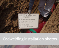
1. CAD WELDING
- Identify the wire to be cad welded and the welded body (protected structure) to determine the size of the mold that matches the size of the welding powder.
- Determine the welding area, remove the coating around 5cm in all directions, and clean the surface with sand paper or other tools.
- Remove about 25mm of the insulation cover of the wire.
- If there is moisture on the surface, welding will not work well, so heat it with a torch to remove the moisture.
- Remove any rust generated during heating with torch.
- Place the wire in the correct position.
- Place the mold and add disk, welding powder, and ignition powder.
- Ignite the IGNITION POWDER (welding occurs when flames appear).
-
Separate the mold and visually inspect the welding condition. If it is satisfactory, lightly strike 4-5 times with a 1 pound hammer.
If the welding joint moves during this process, consider it defective. Repeat the above procedure until the joint is satisfactory.
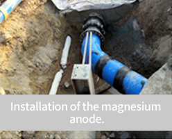
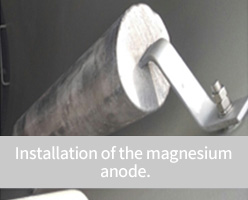
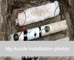
2. Mg-ANODE
- Before applying cathodic protection to the U/G pipeline, underground piping must be installed first.
- Arrange Mg-anodes at regular intervals.
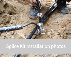
- Connect the main cable and Mg-anode lead cable using a splice kit.
- The main cable shall be connected to the negative(-) cable in the test box.
3. Procedure for Potential Measurement
-
Natural Potential Measurement
(Record a result) -
Protective Potential Measurement
(Record a result)
4. Potential Measurement Method
Potential measurement is performed using a potential measuring instrument (multi-meter) and a reference electrode and is measured as follows.
- Connect the lead cable of the Ref. Electrode to the (-) terminal of the measuring instrument.
- Connect the measuring lead cable of the pipe to the (+) terminal of the measuring instrument.
- Ensure that the reference electrode makes contact with the surface layer of the ground directly beneath the pipeline (In case of using portable ref. electrode).
5. Protective Potential Range
The potential criteria for Cu/CuSO4 Ref. Electrode are set to be below (-)0.85V (increasing in numerical value), and the limits for the minimum and maximum values are as follows:
Minimum value: Below (-)850[mV] / Maximum value: (-)2,500[mV]